
Acopian
Acopian 5E15D25 Regulated DC to DC Converter, 5 V Input, Dual 15 V Output at 0.25 A
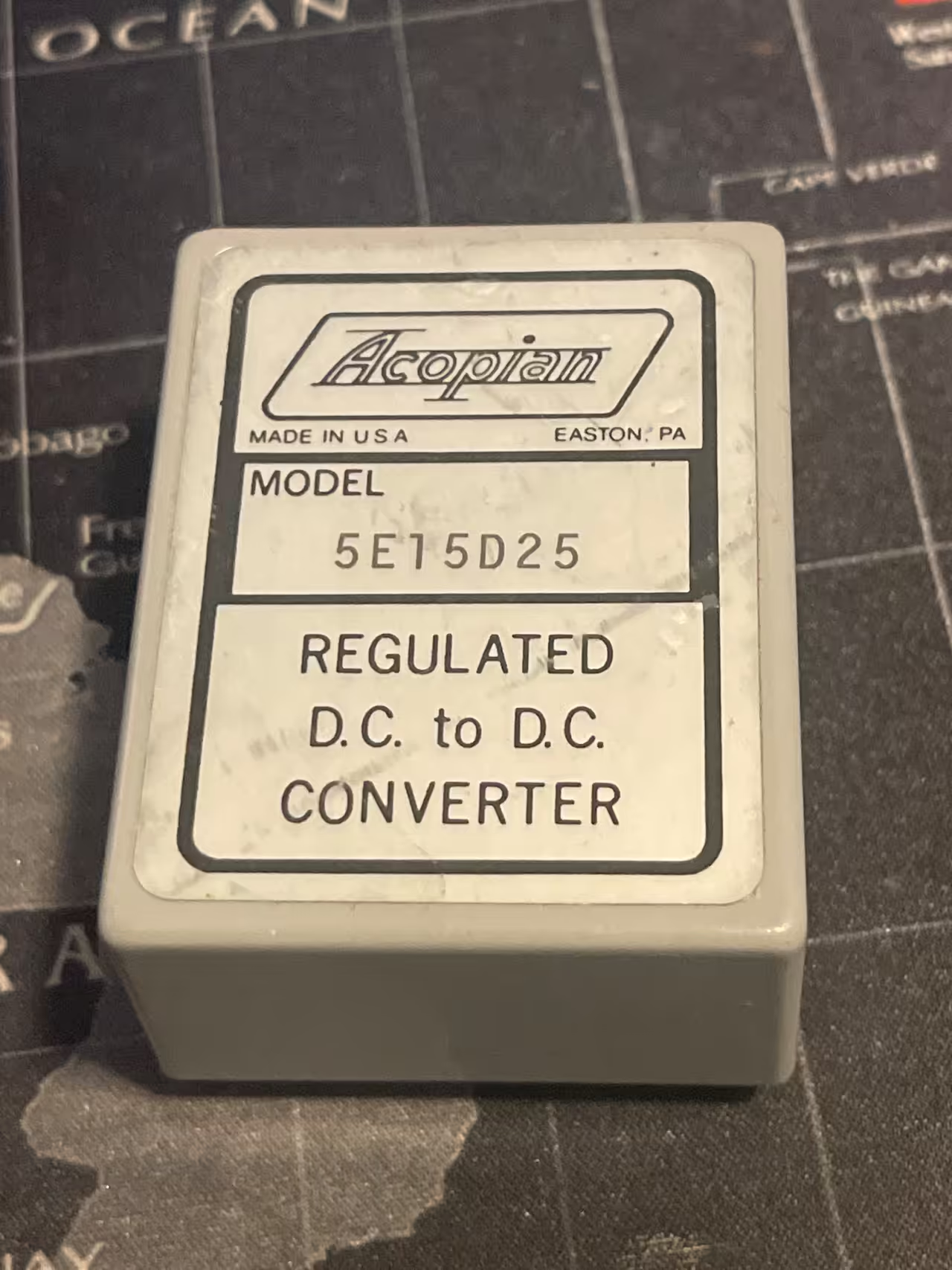
- 3 photos
Never used. The original pack has been opened, or the quantity was split off a full reel or tube. Leads are original and unclipped.
New old stock, open stock on the grading scaleSend the quantity you need. You get a quote back with shipping before anything is charged.
Video
Filmed on the bench. Sound is stripped from product clips.
- 0:10
Specifications
| Specification | Value |
|---|---|
| Identification | |
| Part number | 5E15D25 |
| Manufacturer | Acopian |
| Condition | New old stock, open stock |
| Date code | Not recorded |
| Package | Encapsulated potted module, PCB mounting pins, Acopian ESC-10 case |
| Country of origin | United States |
| Family | Mini encapsulated DC to DC converter |
| Stock number | RH22QSCQ |
| Overview | |
| Manufacturer part number | 5E15D25 |
| Type | Regulated DC to DC converter, encapsulated module |
| Input | |
| Input voltage | 5 V DC nominal |
| Input voltage tolerance | Nominal plus or minus 10 percent |
| Output | |
| Output voltage | Plus 15 V and minus 15 V, dual tracking |
| Output current | 0.25 A per rail, held from 40 C to 71 C |
| Regulation | |
| Line regulation | Plus or minus 0.02 percent |
| Load regulation | Plus or minus 0.05 percent |
| Output ripple | 1 mV rms, 50 mV peak to peak |
| Circuit | |
| Switching frequency | 20 kHz minimum |
| Isolation | |
| Input to output isolation | 500 V DC, 100 megohms |
| Protection | |
| Overload protection | Electronic current limiting with automatic recovery |
| Environment | |
| Operating temperature | Minus 20 C to 71 C |
| Storage temperature | Minus 40 C to 85 C |
| Physical | |
| Mounting | Square section pins along two edges of the case, for PC board mounting |
| Terminal markings on the case | Plus DC, INPUT, a minus beside it, and T/C at one corner |
| Provenance | |
| Inspection stamp | Green QC label reading ACCEPTED 0298, an inspection date of February 1998 rather than a manufacturing date code |
About this part
An Acopian 5E15D25 regulated DC to DC converter, potted, made in Easton, Pennsylvania. New old stock, never installed. The case label gives the model, the line REGULATED D.C. to D.C. CONVERTER, and MADE IN U.S.A.
Read the model number left to right, because one field of it is the one that ruins circuits when it is misread. 5 is the nominal input, 5 V DC. 15 is the output. The D rather than an E marks a dual tracking output, so it gives plus 15 V and minus 15 V about a common return, and 25 is the current in hundredths of an amp. Acopian still catalogues the model.
Feed it 5 V and you get a quiet split rail: line regulation of plus or minus 0.02 percent, load regulation of plus or minus 0.05 percent, ripple of 1 mV rms. That is why these turn up powering op amp front ends and the analogue half of a board that already carries a 5 V logic bus.
Input to output isolation is 500 V DC at 100 megohms, so the output can sit clear of the input bus. Overload is current limiting that recovers on its own, and the 0.25 A holds from minus 20 C to 71 C.
It stands on square section pins along two edges of the case, and the input is legended on the case itself: plus DC, INPUT, a minus beside it, and T/C at one corner. A green inspection label reads ACCEPTED 0298. Check the potting for cracks and the pins for corrosion, then bring it up on a current limited 5 V bench supply and read both rails.
Questions about this part
What voltage does this take in? The model number has both a 5 and a 15 in it.
It takes 5 V DC in. In an Acopian DC to DC model number the input comes first, before the E, and the output comes after it. So 5E15D25 is 5 V in and 15 V out, not the other way round. Getting this backwards is the expensive mistake with this family, because the sibling parts 12E15D25, 15E15D25 and 24E15D25 all put out the same plus and minus 15 V from a different input. Read the digits ahead of the E and match them to your bus before you wire anything.
How does the rest of the model number decode?
5 is the nominal input in volts. E separates the input from the output. 15 is the nominal output in volts. D says the output is dual tracking, where the single output version of the same converter carries an E in that position instead. 25 is the output current in hundredths of an amp, so 0.25 A. Acopian uses the same grammar across the range: 5E12D30 is 5 V in and plus and minus 12 V out at 0.3 A, and 24E15D25 is the 24 V input version of this converter.
Is the output really bipolar, or is it two isolated rails?
It is a dual tracking output, which means plus 15 V and minus 15 V measured against a common return, with the two rails held together as the load changes. That is the arrangement analogue circuitry wants: op amps, comparators and instrumentation amplifiers all expect a symmetrical supply about a shared ground. Each rail carries 0.25 A.
How does it mount, and are the pins marked?
It is a PC board part. Square section pins run along two edges of the potted case, so it drops into a board rather than taking wires under screws. The input side is legended on the case itself, plus DC and INPUT with the minus beside it, and there is a T/C marking at one corner, so you can confirm the polarity against your layout with the module in your hand instead of working from a drawing. The catalogue case size for this model is ESC-10.
What was a converter like this used for?
Boards that already had a 5 V logic bus and needed a clean analogue supply for part of the circuit. Rather than run separate rails the length of a rack, a designer would drop one of these next to the analogue section and generate plus and minus 15 V locally. The 500 V DC input to output isolation is the other half of the reason: the analogue ground can be lifted clear of a noisy digital return instead of sharing it.
Does an unused potted supply from storage still work?
Better than most old power supplies. Everything is encapsulated, so there is no exposed electrolytic drying to air, no fan bearing and no relay contact to oxidise, and the module was never run warm. What ages in storage is the outside: pin corrosion, and occasionally a crack in the potting compound from a knock or a hard temperature swing. Both are visible on inspection, which is the point of buying one that was never fitted.
How should I test it before I put it in a circuit?
Bring it up on a current limited bench supply set to 5 V, with the limit somewhere around 2 A, feeding the pins marked plus DC and INPUT. With no load on the output you should read close to plus 15 V and minus 15 V and see a modest quiescent draw. Then load each rail toward 0.25 A and check that both rails hold and stay together. Only then wire it to anything you care about.